


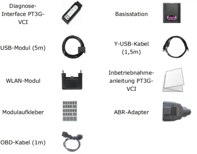
What does the Porsche VCI diagnostic interface include?
2.TECHNICAL DATA OF THE DIAGNOSTIC INTERFACE PT3G-VCI
Module interface: mini USB socket
Power consumption: approx. 5W in operation
Storage temperature: -20 ° C… + 85 ° C
Operating temperature: -20 ° C… + 40 ° C
Power supply: 8 … 18V via diagnostic interface (OBD)
Power consumption
with WLAN module
via diagnostic interface
Normal operation: 300mA / 13.8V,
Shutdown stage 1: 250mA / 13.8V
Shutdown stage 2: 5mA / 13.8V
RAM: 256MB DDR RAM
Permanent memory: 16MB NOR, 4 GB NAND flash
Dimensions: 110 x 48 x 25 mm (LxWxH)
Weight: 90 g
Vehicle interfaces:
High speed CAN
according to ISO 11898-2 o CAN 2.0B with 11- and 29-bit identifier
maximum data rate 1Mbit / s
Low speed CAN
maximum data rate 125kbit / s
-according to ISO 11898-2 Vehicle Ethernet
according to ISO 13400
maximum 100Mbit / s
Ethernet activation switchable
K line
for 12V vehicle systems
according to ISO 9141-2 (max.sink current 300mA)
maximum data rate 125kbit / s
510 ohm line pull-up (can be deactivated)
KL30 voltage measurement
KL15 voltage measurement
Voltage measurement at pin 8 and 9 of the diagnostic connector
3.WLAN MODULE
With the WLAN module, the PT3G-VCI is able to establish a direct
connection via the WLAN interface to the diagnostic device or to the
corresponding infrastructure of the workshop network. For this The WLAN
module supports the modes infrastructure and direct connection (WLAN
access point).
TECHNICAL DATA OF THE WLAN MODULE
Network interface: WLAN 802.11 a / b / g / n 2T2R 300Mbit / s, 2.4 GHz and 5 GHz
Client mode (WPA2-PSK, WPA2-EAP / TLS)
AP mode (WPA2-PSK)
VAS interface: mini USB plug
Storage temperature: -20 ° C… + 85 ° C
Operating temperature: -20 ° C… + 40 ° C
Dimensions: approx. 46 x 48 x 25 mm (WxDxH)
Weight: 22 g
DIAGNOSTIC DEVICE SYSTEM REQUIREMENTS
For the diagnostic device with which the PT3G-VCI is to be configured via the base station
the following system requirements are met:
Operating system: Windows 7, 8.1 (32 & 64 bit)
PIWIS Tester III
Interfaces: 2 x USB 2.0 (or higher, see PIWIS Tester III)
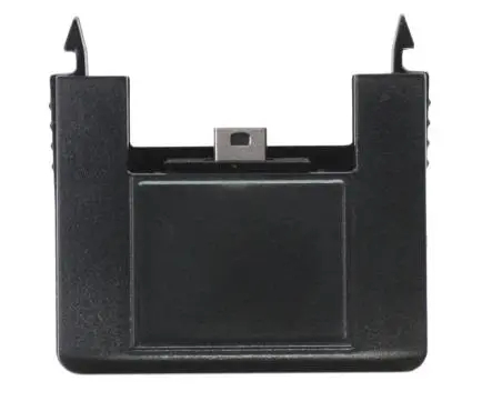
4.BASE STATION
The base station is used to configure and self-test the PT3G-VCI. It is
connected to the diagnostic device using the included Y USB cable.
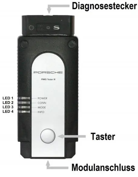
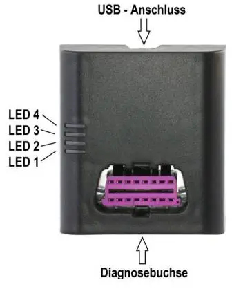
The base station has 4 green LEDs on the top.
TECHNICAL DATA OF THE BASE STATION
Diagnostic device interfaces: USB 2.0 high speed, 480Mbit / s
(Need two USB interface data cables to provide power)
VCI interface: diagnostic socket
Power consumption: Without PT3G-VCI: 0.25W
with PT3G-VCI: 5W
Storage temperature: -20 ° C… + 85 ° C
Operating temperature: -20 ° C… + 40 ° C
Dimensions: 80 x 90 x 36 mm (WxDxH)
Weight: 146 g
more information at: https://www.cnautotool.com/goods-6976-Porsche-Tester-III-Diagnostic-Tool-Piwis-3-Software-Installed-Laptop.html